Please visit us at booth no.: B12
Your Realiable Partner
Please visit us at booth no.: B12
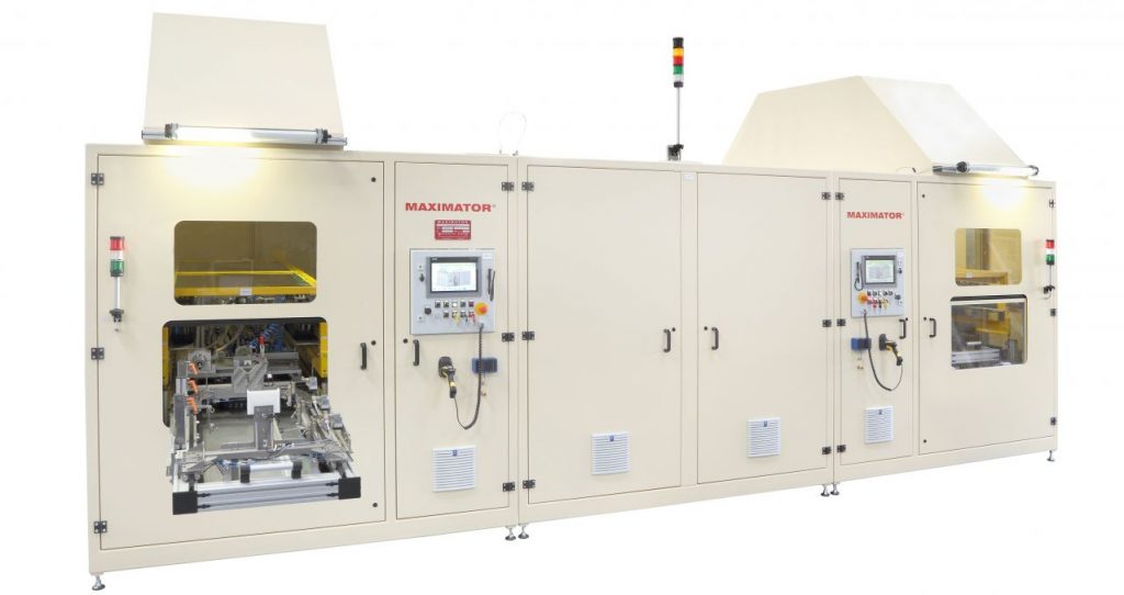
Compared with liquid fuels, natural gas is a cost-efficient and more environmentally friendly propulsion option. Motor vehicles powered by natural gas or hydrogen require special fuel tanks that need to be light, but simultaneously extremely strong, because the gas they contain is subject to high pressure. In order to be able to ensure that such tanks operate safely, manufacturers need to test them in terms of pressure resistance and leak-tightness. For one such manufacturer, Maximator GmbH in Nordhausen, Germany has developed a special pressure testing system, the world’s first process-optimized end-of-line test stand for large-volume composite tanks.

The company, one of the leading suppliers of systems and components for high-pressure technology, has equipped the system designed for series pressure testing of type IV composite tanks with a number of special features, such that it can be called the world’s first process-optimized end-of-line system for this application area. The systems point of use is at the end of a production line (EOL – end of line), its task being the 100% testing of vehicle tanks made of plastic with CFRP/GFRP casing in accordance with the specifications set out in ECE R110 for compressed natural gas (CNG)-powered vehicles. The system can accept large-volume tanks up to 1.4m in length and test them at a pressure of up to 350 bar in one work cycle. The system could also be converted with few specific modifications for the hydrogen field and hence testing in accordance with EC79/2009 for hydrogen-powered (H2) vehicles.
The test procedure is process-optimized, which is expressed in very short clock times. All the operator needs to do is place the tanks in a holding fixture, push this fixture into the test chamber, start the test program and remove the tanks again after the test. The progress of the test can be tracked through panes made of safety glass. In the test chamber, the tanks are automatically arranged for each of the cycles that follow one another – filling of the test fluid water, pressurization, and strength as well as leak-tightness test, draining and drying – such that they proceed at high speed. The pressure intensifier, equipped with a special control developed by our engineering team in-house, enables highly reproducible pressure generation. The deviation of the actual pressure value from the target value is less than 1%.
The system is intended for testing composite tanks, i.e. tanks that are composed of several materials. In the present case, the tanks are made of plastic enveloped and reinforced by several layers of carbon fibers. Components made of composites are extremely strong with a relatively low own weight and are therefore mainly used in aerospace technology, but also increasingly in motor vehicle technology; in fact, anywhere where high strength needs to be combined with low weight. This requirement can be found in virtually all modern structural lightweight applications, an example of which is provided by tanks for vehicles propelled with natural gas or hydrogen. For example, municipal transport services are increasingly replacing diesel-powered buses by those propelled with natural gas, as this drastically reduces the particulate emissions typical of diesel drives.
Since as much gas as possible should be stored, it is added to the tanks in compressed form, which means that they are subject to high internal pressure. In the first case (CNG), this pressure is up to 260 bar, while in the second case (H2) it is up to 700 bar. Compared with steel tanks, the stand-out feature of composite tanks is, as already mentioned, their relatively low weight; they are also highly resistant to environmental influences and never rust.
Maximator also operates a state-of the-art laboratory at its head office in Nordhausen, Germany, where it not only carries out its own development activities, but also a wide range of tests as a service. The technical equipment has recently been enhanced, which means that tests on large-volume composite components (up to 500 litres capacity and 4m long) can now also be conducted. It is possible, while testing a tank, to record its expansion behaviour in longitudinal and circumferential direction to accuracies of 0.1 mm using laser-optical expansion measurement. In the case of burst tests, tank failures can be recorded with the use of high-speed cameras to help determine failure modes. In addition, the new test stand in the Nordhausen service centre enables composite tanks to be placed under mechanical load (torsion and bending) in burst or pressure load change tests. This gives rise to informative insights into the burst behaviour of test specimens, which is advantageous to component assessment and helps to reduce development times.
The test opportunities are likely to be of particular interest to companies in the automotive, general mechanical engineering and energy technology (CNG, H2) fields, as well as processors of composites and companies in the aerospace industry.
(source: https://www.maximator.de)
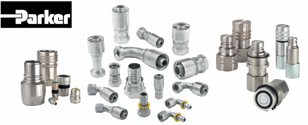
 OEMs and fitting manufacturers are constantly finding new ways to stump us with different threads and new ways to seal them. Generally, however, when making hydraulic fitting connection choices today, there are several features to research and understand for your application. We highlight connections, attachment styles and the 5 most important factors you need to consider for hydraulic fittings.


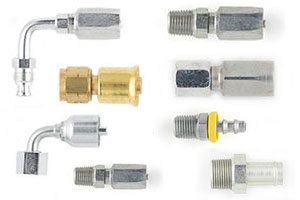
Below are the five factors you should consider when selecting the right hydraulic fitting for your application:
At the end of the day, all hydraulic fittings are only as good as the assembler who installed them. A general rule of thumb is to connect a hose with the least amount of connections possible. There are proper assembly procedures for each of the fitting styles, and strict adherence to those steps makes the difference between a solid connection and a problem waiting to happen.
(source: http://blog.parker.com)
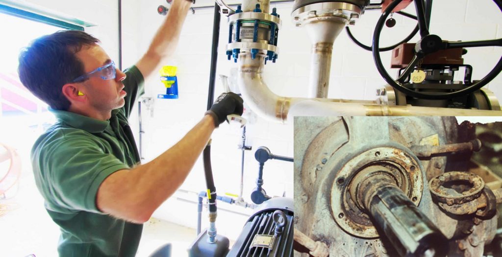
Did you know most bearing failures are not caused by manufacturer’s defect? From not enough grease to too much grease, or improper repairs by an unauthorized shop – our service technicians have seen it all.
Regardless of the cause, bearing failure puts your operation at risk for unscheduled downtime and repairs.
Bearing failure can be prevented with proper maintenance and monitoring. Included below are some of the most common causes and solutions for preventing bearing failure in your liquid ring pump or compressor.
| POSSIBLE CAUSES | SOLUTIONS |
|
|
| POSSIBLE CAUSES | SOLUTIONS |
|
|
| POSSIBLE CAUSES | SOLUTIONS |
|
|
| POSSIBLE CAUSES | SOLUTIONS |
|
|
(source: http://www.gdnash.com/)